
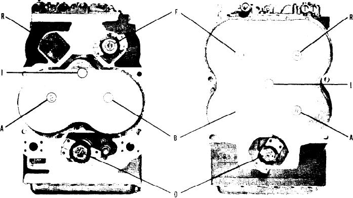
FIG. A - TRANSMISSION ASSEMBLY SHAFT IDENTIFICATION
For purpose of identification, illustration above indicates by alphabetical
d e s i g n a t i o n the individual shaft group location in transmisson. Code to
a l p h a b e t i c a l designation is given below. Alphabetical designation also
appears in heading of each shaft group covered in parts listings herein.
A-Second & Fourth Drive Shaft Group
B-First & Third Drive Shaft Group
F-Input Drive Shaft & Forward Clutch Group
I-Idler Shaft Group
O-Output Shaft & Disconnect Assembly Group
R - R e v e r s e Drive Shaft Group
-6-