TM 5-3805-258-10
OPERATOR’S COMPARTMENT
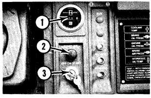
Operator Panel
1. Service Meter — Indicates
the total operating hours of the
engine. It should be used to
determine service intervals.
2. Starting Aid – Depress the
button when starting aid is required
during cold weather. This
releases a premeasured amount of
ether into the air intake.
3 . P o w e r S w i t c h – O F F – no
electrical power to the cab.
ON — all circuits in the cab are
operational.
START — starts the engine, key
returns to the ON position when
released.
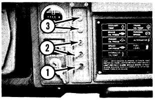
Light Switches
1. Panel Lights — Move the
switch to the center position to
turn on the panel lights.
Running Lights — Move the
panel lights switch to the right
position to turn on the running
lights (front and rear).
2. Flood Lights – Move the
switch to the right position to turn
on the flood lights for
illumination of the work area.
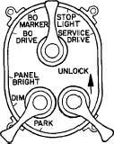
3. Blackout Lighting Switch – The blackout lighting
switch is located on the left hand console.
The mechanical lock should be engaged at all
times to keep the main switch in the position
selected.
When the main switch is placed in the BO DRIVE
position, the blackout driving lamp and blackout
tail lamps will illuminate, and the warning horn,
warning lamp, backup alarm, and primary
steering flow indicator circuits are active.
When the STOP LIGHT position is selected, the
stop lights will illuminate when the brake pedal is
pressed. The stop light switch is not functional
when the main switch is in any other position.
In SERVICE DRIVE position, the service headlamps
and tail lamps will illuminate.
The auxiliary switch controls instrument panel
lighting brightness. Instrument panel lights are off
when switch is in the PARK position.
20