TM 5-3805-258-24-1
- DIRECT INJECTION VEHICULAR ENQINE
SPECIFICATIONS
WITH SCROLL FUEL SYSTEM
FLYWHEEL RUNOUT
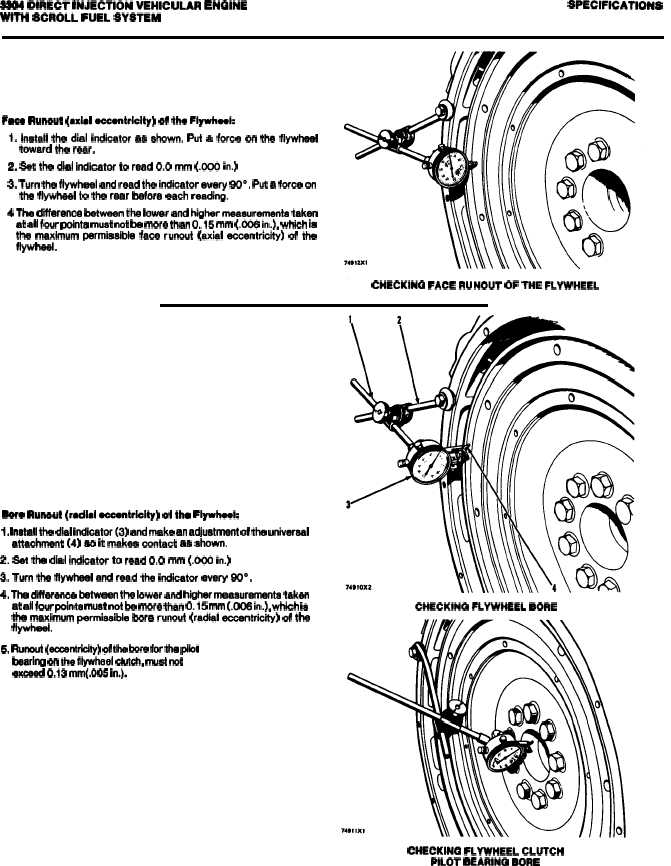
Faaa Runout (axial aaaentriclty) of tho Flywheek
1. Install the dial indicator aa shown. Put a force on the flywhaat
toward the rear.
2. Sat the dial indicator to read 0.0 mm (.000 in.)
3. Turn the flywheel and read the indicator every 90°, Put a force on
the flywheel to the rear before each reading.
4 The difference between the lower and higher measurement taken
at all four points must not be more than 0.15 mm (.006 in.), which ia
the maximum parmiaeible face runout (axial eccentricity) of the
flywheel.
CtlECKINQ FACE RUNOUT OF THE FLYWHEEL
Sere RunOut (radial eccentricity) of the Flywhaek
1. Install the dial indicator(3) and make an adjustment of the universal
attachment (4) so it makea contact aa ahown.
2. Set the dial indicator to read 0.0 mm (.000 in.)
3. Turn the flywheel and read the indcator every 90°.
4. The difference between the lower and h~her meaauramants taken
at all four pcinta must not be more than 0.15 mm (.CK16 in.), wh~h is
the maximum parmiaaible bore runout (radial eccentricity) of the
flywheel.
5. Runcut @centrklfy) of the bore for the pfbt
bearing cn fhe flywheel clutch, must not
exceed 0.13 mm(.fJ05 in.).
CHECKfNG FLYWHEEL BORE
CHECKfNG FLYWHEEL CLUTCH
PILOT BEARfNG BORE
2-26