TM 5-3805-258-24-1
9506 AIR SYSTEM AND BRAKES
SPECIFICATIONS
EMERGENCY AND PARKING BRAKE
ADJUSTMENT
WARNING
Before making any tests or adjustments on the brske
system, stop the mechine on Ieval ground and lower the
bucket to the ground. Move tha control knob for the parking
brake to the ON position. Put blocks in front of and behind
the wheels. Permit only one man on the machine. Keep all
other personnel away from the machine. Never disconnect
any air or brake fluid Iinea in the brake system until all
pressure is removed. Failure to remove this pressure will
have a sudden release of air or brake fluid under high pres-
sure. This can cause injury to personnel. To remova the
pressure from the brake system: Engage the parking brake.
Stop the engine. Push on either brake pedal many times until
thara is no more braka air pressure. When the air prassure
has been removed from the air circuit, there will be no pres-
sure in the brake hydraulic circuit.
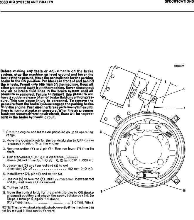
1. Start the engine and let the air pressure go up to operating
range.
2. Move the control knob for the parking brake to OFF (brake
released) position, Stop the engine.
3. Remove cotter (4) and pin (6). Remove lever (7) from ita
shaft.
4. Turn starwheel (10) to get a clearance, between
shoes (9)and drum(8), of 0.25 t 0.12mm (.010 i .005 in.)
5. Loosen nut (2) and turn rod end (3) to get
dimension (A) of . . . . . . . . . . . . . . . . 102 mm (4.o in,)
6, Install lever (7), pin (6) and cotter (4),
7. Use nut (5) to turn rod (1) until free movement between rod
end (3) and lever (7) is removed.
8. Tighten nut (2).
9. Move the control knob for the parking brake to ON (brake
engaged) position and check the stroke [distance (B)]. Do
Steps 1 through 8 again if distance
(B) ia more than . . . . . . . . . . . . . . . . . . . . . . . . . . . . . . . . . . . . . . 19.o mm (.75 in.)
NOTE: The parking brake is adjusted correctly if the machine can
not be moved in first sDeed forward.
2-60


