TM 5-3805-258-24-1
WW HYDRAULIC SYSTEM
SPECIFICATIONS
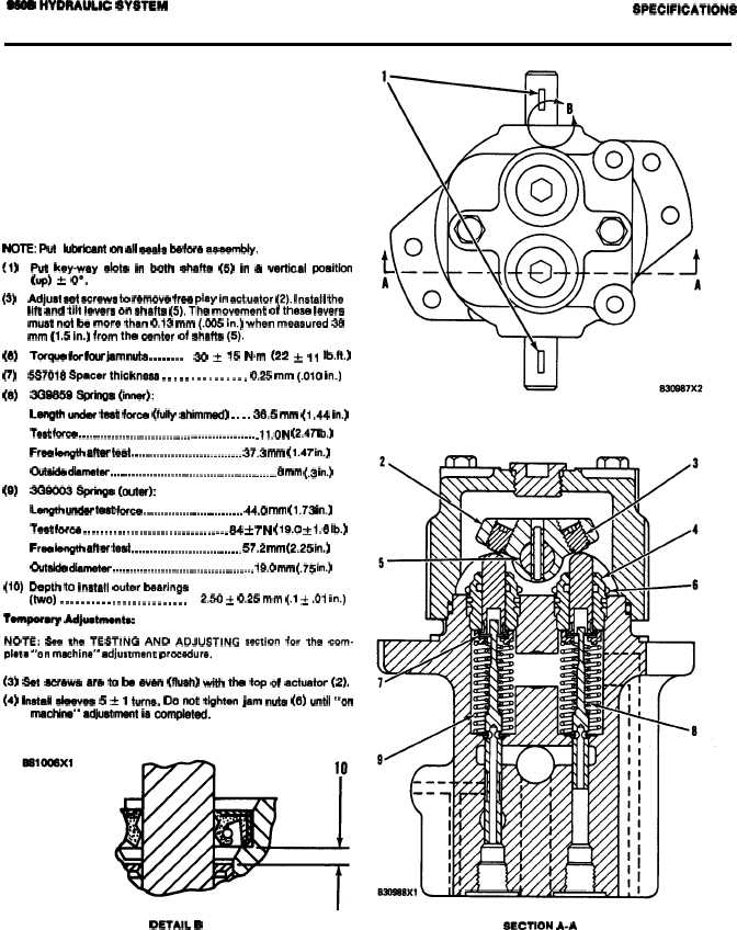
LIFT AND TILT PILOT VALVE
(1U2172)
NOTE Put lubricant on all seals before aaaemtsly.
(1)
Put key-way dots in both chaffs (5) in a vertical position
(up) * OO.
(3)
(6)
(7)
(8)
(9)
(lo)
Adjust eat screws to remove free play in actuator (2). Install the
lift and tilt levers on shafts (5), The movement of these levers
must not be more than 0.13 mm (.005 in.) when measured 38
mm (1.5 in.) from the center of shafts (5).
Torque for four jam nuts . . . . . . . .
30 ~ 15 N.m (22 & 11 lb@ftJ
5S7018 Spacer thickness . . . . . . . . . . . . . . . 0.25 mm (.Olt) in.)
3GS8598pringe (inner)
Length under teat force (fully ahimmad) . . . . 36.5 mm (1 .44 in.)
Teat fCWCO . . . . . . . . . . . . . . . . . . . . . . . . . . . . . . . . . . . . . . . . . . . . . . . . . . 11.0 N (2.47 lb.)
Fraa length after teat . . . . . . . . . . . . . . . . . . . . . . . . . . . . . . . 37.3 mm (1.47 in.)
@M& d&lWtW . . . . . . . . . . . . . . . . . . . . . . . . . . . . . . . . . . . . . . . . . . . . . . . 8 mm (.3 in.)
3G90038pringa (outer)
L&tgth under teat force . . . . . . . . . . . . . . . . . . . . . . . . . . . . 44.0 mm (1.73 in.)
Teet fCW@ . . . . . . . . . . . . . . . . . . . . . . . . . . . . . . . . . . 8.4 ~ 7 N (19.t) ~ 1.6 lb.)
Fraa length after teat . . . . . . . . . . . . . . . . . . . . . . . . . . . . . . . 57.2 mm (2.25 in.)
OUtSW diameter . . . . . . . . . . . . . . . . . . . . . . . . . . . . . . . . . . . . . . . . 19.0 mm (.75 in.)
Depth to install outer bearings
(two) . . . . . . . . . . . . . . . . . . . . . . . . .
2.50 * 0.25 mm (.1 * .01 in.)
Tamparary Mjuatrnentw
NOTE: See the TESTING AND ADJUSTING section for the com-
plete “on machine” adjustment procedure.
(3) Sat acrawa are to be even (flush) with the top of actuator (2).
(4) Install alaavea 5 t 1 turns. Do not tighten jam rsute (6) until “on
machine” adjuatmertt ie completed.
DETAIL B
SECTION A-A
2-63