TM 5-3805-262-20
INSTALLATION
(1)
(2)
(3)
(4)
( 5)
(6)
(7)
(8)
(9)
( l 0)
(11)
(12)
(13)
(14)
(15)
(16)
Position backing plate (12) on transmission housing.
Install four capscrews (11). Tighten to 81 to 97 lb-ft.
Install brake shoe lever (9) and roller (10).
Position two shoes and linings (8) on backing plate (12) and attach bot-
tom spring (7) to each shoe and lining (8).
Hold shoes and linings in place and attach top spring (7) to each shoe
and lining (8).
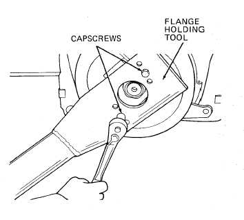
Position flange (6) on brake drum (5) and install four capscrews (4).
Tighten capscrews to 41 to 49 lb-ft.
Push shoes and linings (8) together and install brake drum (5) and flange
(6) on transmission output shaft; rotate brake drum as necessary to aline
splines in flange with splines on output shaft.
I n s t a l l n e w 0 - r i n g ( 3 ).
Install washer (2) and new locknut (1). Do not tighten locknut (l).
Install flange holding tool on
flange (6) using two 7/16-20NF
by 1 inch long capscrews.
Tighten lock nut (1) to 450 to
7 0 0 l b - f t.
Remove two 7/16-20NF capscrews
and flange holding tool.
Connect parking brake link to
brake shoe lever (page 7-10).
I n s t a l l c e n t e r d r i v e s h a f t
(page 6-42).
F i l l t r a n s m i s s i o n w i t h o il
(page 6-6).
Remove chocks from wheels.
7-7