TM 5-3805-262-20
INSTALLATION (SHEET 2 OF 2)
(18)
(19)
(20)
(21)
(22)
(23)
(24)
(25)
(26)
(27)
(28)
(29)
(30)
(31)
(32)
(33)
Install clamp (9) and clamp (4) on hose (8).
Connect hose (13) to heater core tube by pushing onto core tube as far as
i t w i l l g o .
Connect hose (8) to tube (11) by pushing it onto tube as far as it will
go. Connect other end of hose to HEAT CONTROL valve port. If necessary,
adjust length of hose by pulling it farther out of or into tube (11).
Position clamps (4, 10, and 12) on hose ends and tighten securely.
Position clamp (9) on hose (8) by aligning clamp mounting hole with asso-
ciated mounting hole in heater console
Install and tighten capscrew (7),
lock washer (6), and nut (5) to
secure clamp (9) to heater console
(38) .
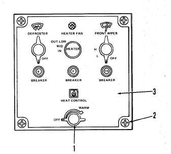
Install cab switch panel (3) on
heater console taking care not to
disconnect or pinch wiring between
switch panel and heater console.
Install and tighten four screws
(2) to secure switch panel (3) to
heater console.
Install HEAT CONTROL knob (1) by
pushing firmly onto HEAT CONTROL
v a l v e s h a f t .
Open heater water shut-off valves
at water pump and engine.
Connect battery ground cable (page
( 3 8 ).
5-151) .
Start engine and operate at idle speed for three minutes. Turn off engine
and check coolant level at radiator (page 4-71). Add coolant as neces -
s a r y .
Start engine, operate at idle speed, and check for coolant leaks at hose
and tube connections to heater and engine. Tighten clamps as necessary if
leaks are seen.
Set HEATER FAN control to LOW position and HEAT CONTROL to WARM position.
Check that heater fan operates and warm air is blown from heater cover.
Turn off engine. If heater fan does not operate or warm air is not blown
from heater cover, refer to troubleshooting (page 3-165 or 3-168).
Install operator’s seat upper seat support (page 9-32).
Install engine side panels (page 9-17) .
10-45