
TM 5-3805-290-23-1
ELECTRICAL SYSTEM TESTS, INSPECTIONS, AND ADJUSTMENTS - CONTINUED
0013 00
FUEL INJECTION PUMP CIRCUIT TEST - CONTINUED
1.
Check batteries. Measure no-load battery voltage at battery terminals.
Expected Results. The battery voltage is no less 22V.
(1)
If results are OK, proceed to step 2.
(2)
If results are NOT OK, recharge or replace batteries (WP 0077 00). Verify repairs have eliminated prob-
lem.
2.
Inspect electrical connectors and wiring. Refer to Electrical Connectors Inspection (WP 0022 00).
a.
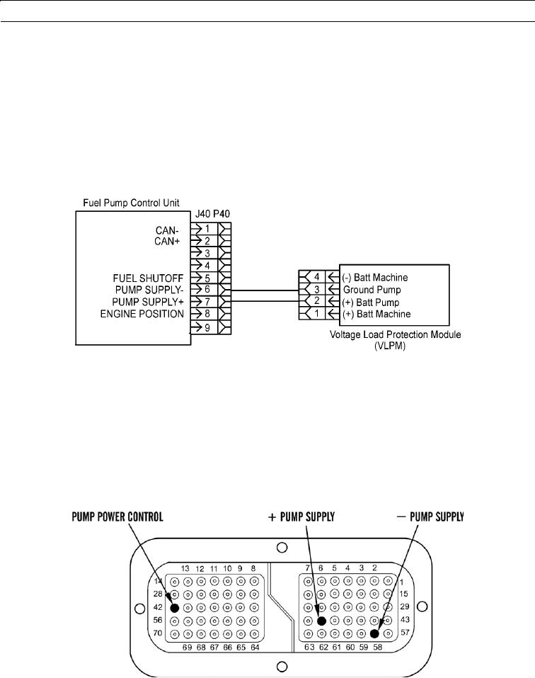
Thoroughly inspect P40:6 Pump Supply (-) and P40:7 Pump Supply (+) terminal connections on fuel pump control
connector.
427-B0720
b.
Disconnect and thoroughly inspect these terminal connections on P20/J20 Machine Interface Connector and per-
form 10 lb (45 N) pull test on each wire in MIC (WP 0170 00):
(1)
P20: 58 (-) Batt Machine
(2)
P20: 48 (+) Batt Machine
(3)
P20: 42 Pump Power Control
c.
Check ECM connector (socket-head screw) for proper torque of 55 lb-in. (6 Nm).
d.
Check harness and wiring for abrasions and pinch points from battery to ECM. Also check harness and wiring for
abrasions and pinch points from engine start switch to ECM.
427-B0721
0013 00-53