
TM 5-3805-291-10
Messenger Reference Guide
Linkage/Cylinder Calibration Menu:
Allows the operator to perform calibration procedures on the linkages and cylinders of the implement on the
machine. The following lever calibrations can be performed using this sub menu:
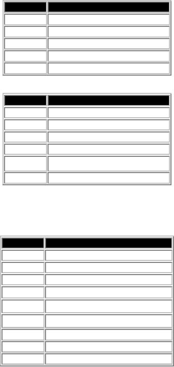
Lift Linkage Position Sensor Calibration:
Step Number
Step and Display String
1.
Press next button to start
2.
Set parking brake
3.
Raise linkage to max position ..'Next'
4.
Place bucket into full rackback ..'Next'
5.
Lower linkage to min position ..'Next'
Tilt Linkage Position Sensor Calibration:
Step Number
Step and Display String
1.
Press next button to start
2.
Set parking brake
3.
Place bucket into full rackback ..'Next'
4.
Lower linkage to min position ..'Next'
5.
Raise linkage to max position ..'Next'
6.
Place bucket into full dump ..'Next'
Valve Calibrations
Implement Raise:
*Set the engine speed to high idle before starting calibration.
Step Number
Step and Display String
1.
Set park brake, unlock implement
2.
Disengage Implement Lockout Switch
3.
Set lift cylinder extension to 450-500mm
4.
Set tilt cylinder extension to 200-250mm
5.
Set Engine Speed to high idle
6.
Release lever ..'Next'
7.
Move lift lever to full raise and hold
8.
CALIBRATING
9.
Release lever ..'Next'
0004 00-50