TM 5-3805-291-23-1
EQUIPMENT DESCRIPTION AND DATA - CONTINUED
0002 00
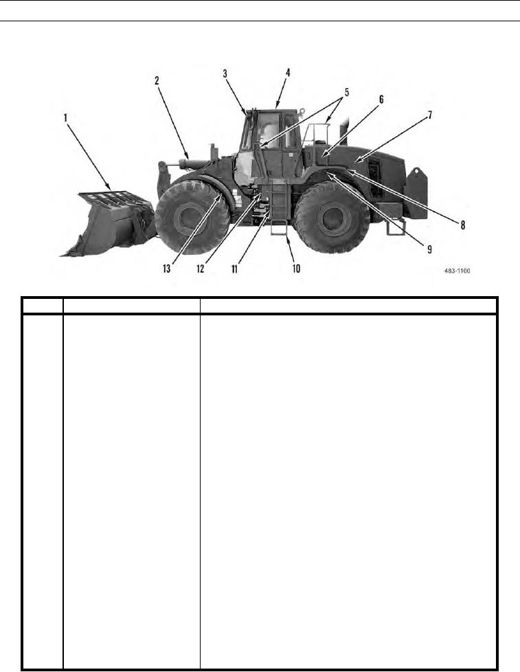
LOCATION AND DESCRIPTION OF MAJOR COMPONENTS
0002 00
KEY
COMPONENT
DESCRIPTION
1
Bucket
Hardened steel bucket has teeth, bolt-on segments, and corner guards.
The Type I machine uses a 4.5 yd3 (3.5 m3) Rock bucket. The Type II
machine uses a 5.0 yd3 (3.8 m3) GP bucket. Refer to Equipment Data
in this work package for more information.
2
Tilt Cylinder
Single hydraulic cylinder tilts work tool.
3
Front Worklights
Illuminate work area to front of machine. Mounted to roof bracket on
both sides of machine.
4
ROPS/FOPS
Bolt-on structure provides rollover and falling object protection for
operator. Must be removed for transport by M870 Series Semitrailer
and AAR rail.
5
Grabhandle/Hand Rails
Provides a handhold for personnel climbing on machine.
6
Hydraulic Tank
Stores hydraulic fluid used in machine hydraulic systems. Contains
sight gage for fluid level check.
7
Hood
Electrically activated tilt design opens for access to engine
compartment.
8
Fender
Located over rear tire, on both sides of machine.
9
Platform
Skid-free surface for gaining access to cab and top of machine. Located
on both sides of machine.
10
Ladder
Provides access to cab and platform. Located at front and rear, on both
sides of machine.
11
Battery Box
Provides protection for batteries.
12
NATO Slave Receptacle
Provides connection point for NATO slave cable to slave start
machine.
13
Fender
Located over front tire, on both sides of machine.
0002 00-3

