
TM 5-3805-291-23-1
THEORY OF OPERATION - CONTINUED
0003 00
STEERING SYSTEM - CONTINUED
d.
LEFT TURN Position.
(1)
When machine is turned left, steering control valve operates in a similar manner to a right turn.
(2)
For a left turn, pilot oil enters left turn pilot port. Pressure oil from steering pump inlet port flows through
metering pump drain passage, then past directional spool. From directional spool, oil flows out of left turn
steering cylinder port.
(3)
Pressure oil then flows to rod end of left-side steering cylinder, and head end of right-side steering cylin-
der.
(4)
Simultaneously, return oil flows from head end of left-side steering cylinder and rod end of right-side
steering cylinder. This causes machine to articulate left.
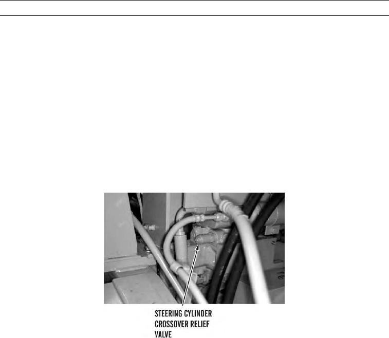
e.
Steering Cylinders Crossover Relief Valve.
N OT E
In the illustration below, the operator's cab is removed for clarity.
427-C1800
0003 00-127