
TM 5-3805-291-23-1
THEORY OF OPERATION - CONTINUED
0003 00
ELECTRO-HYDRAULIC SYSTEM - CONTINUED
b.
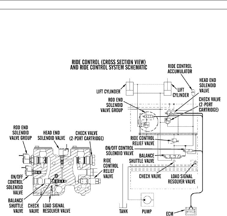
Ride control accumulator is located at articulation joint on right side of front end frame. Accumulator contains a
precharge of nitrogen gas. Ride control valve will control oil flow between ride control accumulator and lift cylin-
ders.
c.
When ride control system is activated and machine travels over rough terrain with a loaded implement, forces of
load act against lift cylinders. When load acts against head end of lift cylinders, oil from head end will try to flow
into accumulator. Accumulator will act as a shock absorber.
427-C1839
0003 00-178