
TM 5-3805-291-23-2
HYDRAULIC OIL TEMPERATURE SENSOR REPLACEMENT - CONTINUED
0083 00
REMOVAL - CONTINUED
4.
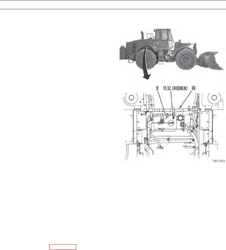
At bottom of hydraulic tank (9), disconnect chassis
wiring harness (10) from hydraulic oil temperature
sensor (11).
5.
Remove hydraulic oil temperature sensor (11) and
O-ring (12) from hydraulic tank (9). Discard O-ring.
INSTALLATION
1.
Apply a thin coat of clean oil to new O-ring (12). Install new O-ring on hydraulic oil temperature sensor (11).
2.
Install hydraulic oil temperature sensor (11) on hydraulic tank (9).
3.
Connect chassis wiring harness (10) to hydraulic oil temperature sensor (11).
4.
Position sound suppression panel (7) on machine and install three washers (6) and bolts (5) on sound suppression panel.
5.
Position accumulator (8) refrigerant dryer (4) and two clamps (3) on machine and install two washers (2) and bolts (1)
on clamps.
6.
Install air cleaner (WP 0030 00).
7.
Fill hydraulic oil tank (WP 0148 00).
8.
Operate machine and verify correct operation of AC and hydraulic system (TM 5-3805-291-10).
9.
Shut down engine (TM 5-3805-291-10).
10.
Check for leaks.
END OF WORK PACKAGE
0083 00-3/(0083 00-4 Blank)