
TM 5-3805-291-23-2
WHEEL AND TIRE ASSEMBLY (FRONT) REPLACEMENT - CONTINUED
0119 00
INSTALLATION - CONTINUED
2.
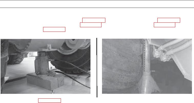
Use Pump, hydraulic ram, hand-driven (Item 56, WP 0232 00) and Puller, hydraulic (Item 53, WP 0232 00) to raise
machine and remove Stand assembly (Item 78, WP 0232 00), Pin, shoulder, headless (Item 48, WP 0232 00), and Repair
tool, special (Item 63, WP 0232 00), as shown, from under machine. Lower machine to ground.
427-C0193
427-C0192
3.
Install front fender (WP 0136 00).
WAR N I N G
Before operating the machine, secure the steering frame lock in the stowed position. DO NOT operate
machine with steering frame lock connected. Failure to lock steering frame lock into the stowed position
before operating can result in loss of steering and injury or death to personnel.
4.
Secure steering frame lock in stowed position (TM 5-3805-291-10).
END OF WORK PACKAGE
0119 00-4