TM 5-3805-291-23-2
RIDE CONTROL ACCUMULATOR MAINTENANCE - CONTINUED
0151 00
DISCHARGING/CHARGING - CONTINUED
Nitrogen Charging Procedure - Continued
7.
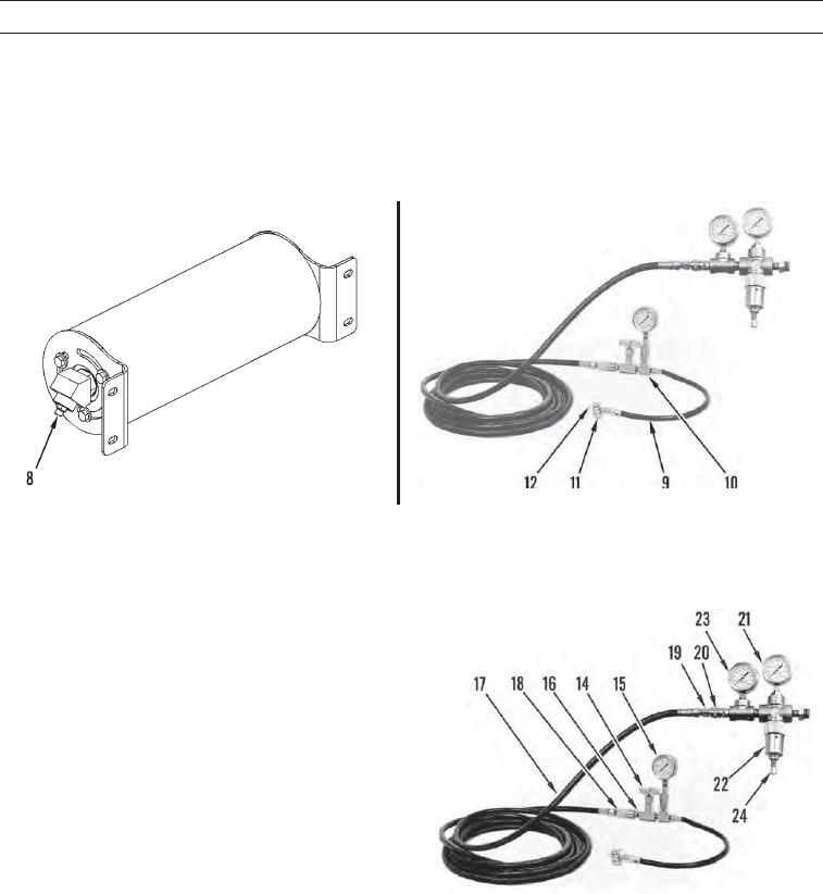
Turn T handle (12) on nitrogen charging chuck (11) counterclockwise. Attach nitrogen charging chuck to nitrogen
charging valve (8).
8.
Connect hose assembly (9) between nitrogen charging chuck (11) and T (10).
427-C1121
427-C1122
9.
Install needle valve (14). Install pressure gage (15) on T.
10.
Install nipple (16) on needle valve (14).
11.
Install coupling assembly (18) on hose assembly (17).
12.
Connect hose assembly (17) to nipple (16) on needle
valve (14). Place open end of hose assembly away
from work area and other personnel.
13.
Open needle valve (14) and turn T handle (12) on
nitrogen charging chuck (11) clockwise.
14.
Raise bucket to maximum height to relieve any addi-
tional nitrogen from ride control accumulator
(TM 5-3805-291-10).
15.
Close needle valve (14).
16.
Lower bucket to ground. Move lift control lever to
FLOAT position (TM 5-3805-291-10).
17.
Shut off engine (TM 5-3805-291-10).
427-C1591-1
18.
Install nipple (19) in hose assembly (17).
19.
Attach open end of hose assembly (17) to coupling assembly (20). Install differential pressure gage (21) in coupling
assembly port directly above pressure regulator assembly (22).
20.
Install differential pressure gage (23) in remaining port next to regulator assembly (22).
21.
Install regulator assembly (22) on nitrogen tank valve. Turn valve on nitrogen tank counterclockwise on tank. Adjust
screw (24) on regulator assembly to set pressure to charge pressure.
22.
Open needle valve (14). Nitrogen pressure should show on pressure gage (15) within 20 seconds.
0151 00-9

