
TM 5-3805-292-23
0073
ADJUSTMENT
00073
WARN I N G
Tracks are designed to run loosely, not tight.
If track is adjusted too tightly, damage islikely to occur to tracks and machine and cause
premature wear to linkage system.
Only place bolts in position A or B (Figure 11).
DO NOT place bolts in position C (Figure 11) or damage is likely to occur to tracks and
machine.
Failure to follow these warnings may result in injury or death to personnel or damage to
equipment.
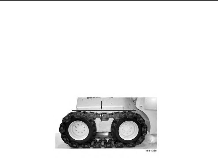
1. Proper track length is achieved when all slack (Figure 10) is at top of tracks, and measures approximately 1 to
3 in. (26 to 76 mm).
Figure 10. Slack.
0073
2. Remove track pad (see Removal in this work package).
3. With one track pad removed and ends of track pulled together, measure distance between two ends of track
and subtract that amount from 10 in. (254 mm). Divide difference by 0.81 in (20.6 mm); result is number of bolt
pairs that need to be moved to position B (Figure 11, Item B).
N OT E
Adjusting twelve pairs of bolts is equal toremoving one track pad, or 10 in. (254 mm).
Use position A (Figure 11, Item A) to lengthen tracks.
Use position B (Figure 11, Item B) to shorten tracks.