• Home
  • Download PDF
  • Order CD-ROM
  • Order in Print
Figure 4. LH Console Connectors.
Figure 6. RH Console.

Field Maintenance Manual For M400T And M400W
Page Navigation
  649    650    651    652    653  654  655    656    657    658    659  
img
. .
TM 5-3805-292-23
0094
INSTALLATION CONTINUED
N OT E
Instrument panel may be installed without removing RH console. Refer to WP 0155.
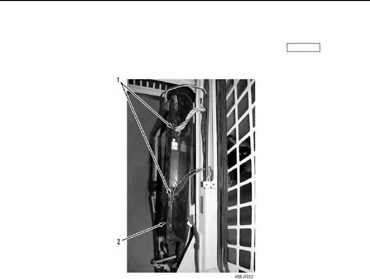
4. Connect two connectors (Figure 5, Item 1) to RH console (Figure 5, Item 2).
Figure 5. RH Console Connectors.
0094
5. Position RH console (Figure 6, Item 2) on cab and install three mounting capscrews (Figure 6, Item 1).
0094-6


Privacy Statement
Press Release
Contact

© Copyright Integrated Publishing, Inc.. All Rights Reserved.