
4
TM 5-3805-292-23
FIELD MAINTENANCE
-
LEFT JOYSTICK CONSOLE REPLACEMENT
0104
REMOVAL, CLEANING AND INSPECTION, INSTALLATION
INITIAL SETUP
Tools and Special Tools
References
0
0
Tool Kit, General Mechanic's (WP 0178, Item
TM 5-3805-292-10
0
33)
TM 5-3805-292-23P, Figure 52
0
0
SATS (WP 0178, Item 30)
0
Equipment Conditions
0
Materials/Parts
Machine parked on level ground (TM 5-3805-
0
Cleaning Compound, Solvent, Type III (WP
292-10)
0
0179, Item 3)
ROPS tilted (WP 0134)
0
0
Rag, Wiping (WP 0179, Item 19)
Dust boot removed (WP 0101)
0
0
Estimated Time to Complete
0
0.7 Hr
0
REMOVAL
000104
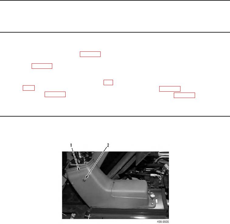
Remove four bolts (Figure 1, Item 2) and console (Figure 1, Item 1) from machine.
Figure 1. Joystick Console Replacement.
0104
END OF TASK