
TM 5-3805-292-23
0114
REMOVAL CONTINUED
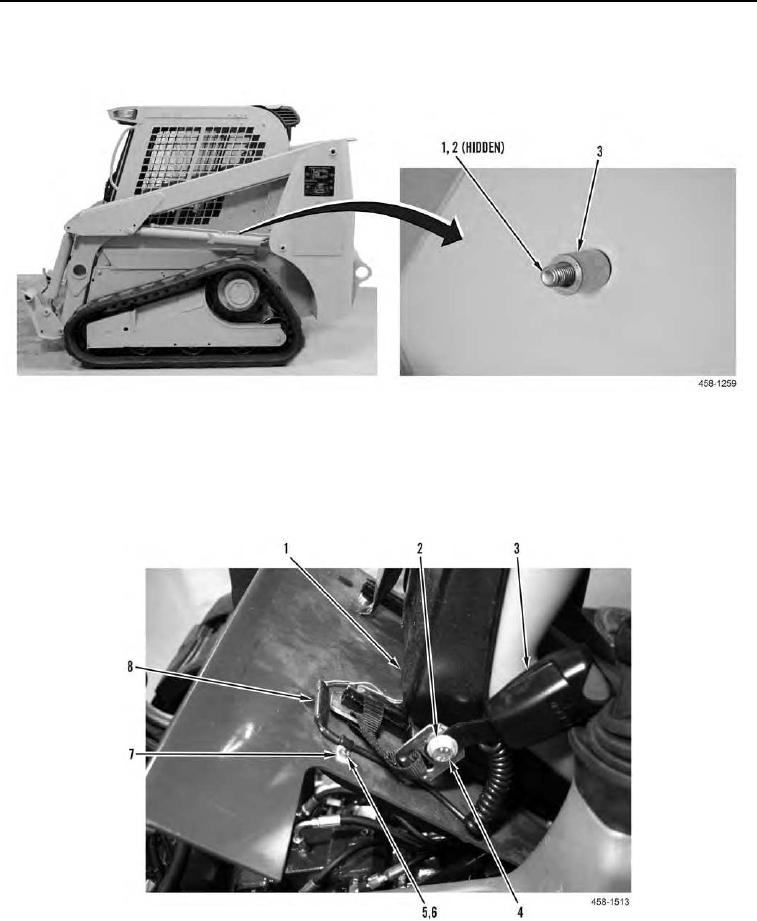
5. Remove shoulder belt retractor (Figure 3, Item 2) and spacer (Figure 4, Item 3) from bolt (Figure 4, Item 1).
Remove bolt (Figure 4, Item 1) and washer (Figure 4, Item 2) from ROPS.
Figure 4. Shoulder Belt Retractor Spacer and Bolt.
0114
6. Disconnect electrical connector (Figure 5, Item 8).
7. Remove nut (Figure 5, Item 6) and bolt (Figure 5, Item 5) from clamp (Figure 5, Item 7).
8. Remove bolt (Figure 5, Item 4) and washer (Figure 5, Item 2) from seat assembly (Figure 5, Item 1).
9. Remove buckle (Figure 5, Item 3) from machine.
Figure 5. Electrical Connector and Buckle.
0114
END OF TASK