• Home
  • Download PDF
  • Order CD-ROM
  • Order in Print
Figure 3. Left Side Window.
Figure 5. LH Console.

Field Maintenance Manual For M400T And M400W
Page Navigation
  807    808    809    810    811  812  813    814    815    816    817  
img
.
TM 5-3805-292-23
0120
INSTALLATION
000120
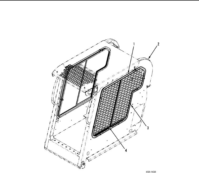
1. Install LH window frame (Figure 4, Item 1) and rubber seal (Figure 4, Item 4) on ROPS assembly (Figure 4,
Item 2).
2. Install bolts (Figure 4, Item 3) on ROPS assembly (Figure 4, Item 2).
Figure 4. Left Side Window.
0120
0120-4


Privacy Statement
Press Release
Contact

© Copyright Integrated Publishing, Inc.. All Rights Reserved.