
TM 5-3805-292-23
0130
REMOVAL CONTINUED
4. Tilt ROPS (WP 0134).
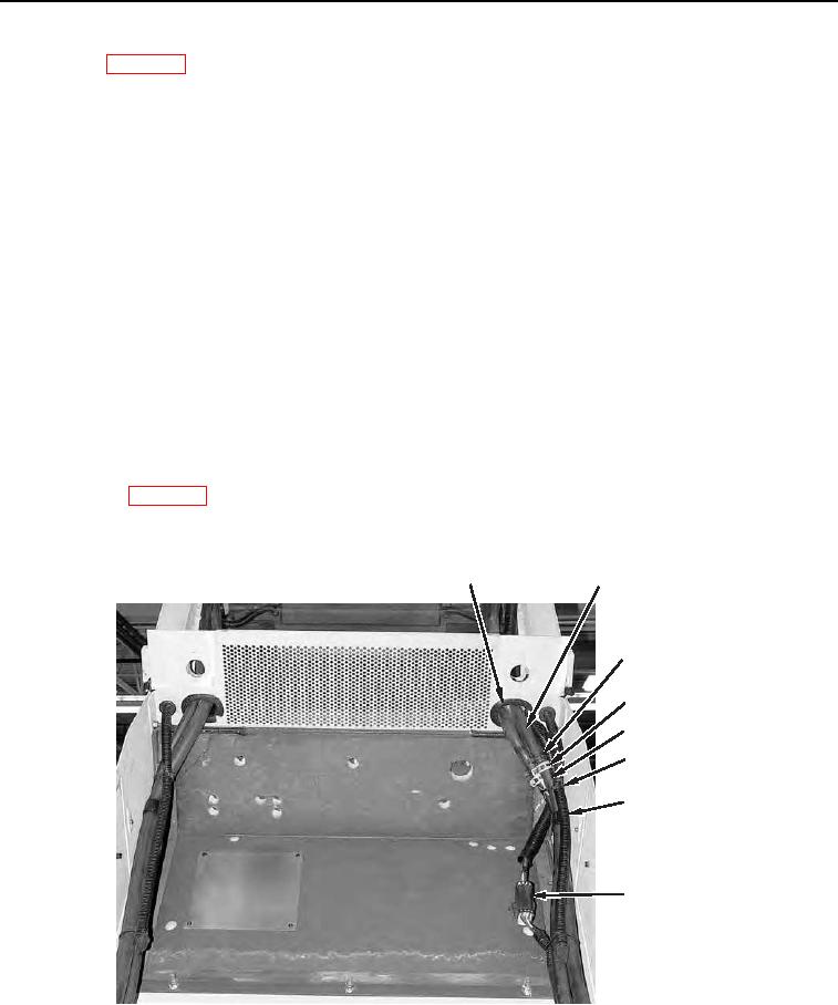
5. Remove tiedown straps (Figure 4, Item 7) from lower heater hoses (Figure 4, Item 6), drain hose (Figure 4,
Item 8), and wiring harness (Figure 4, Item 9). Discard tiedown straps.
N OT E
Tag all electrical connectors to aid installation.
6. Disconnect wiring harness (Figure 4, Item 9).
N OT E
Tag and mark all hoses to aid installation.
Cap all ports and open hoses immediately upon disconnection to prevent dirt from
entering system.
7. Release two hose clamps (Figure 4, Item 5) from lower heater hoses (Figure 4, Item 6) and disconnect two
upper heater hoses (Figure 4, Item 2) from lower heater hoses (Figure 4, Item 6).
8. Remove two hose clamps (Figure 4, Item 3) and tubing (Figure 4, Item 4) from upper heater hoses (Figure 4,
Item 2).
9. Remove two upper heater hoses (Figure 4, Item 2) and wiring harness (Figure 4, Item 9) through hole (Figure
4, Item 1) in body panel.
10. Close ROPS (WP 0134).
1
2
3,4 (HIDDEN)
5
6
7
8
9
458-1140
Figure 4. Wiring Harness, Heater Hoses, Drain Hose, and
Retaining Hardware on Back of ROPS.
0130
0130-4