• Home
  • Download PDF
  • Order CD-ROM
  • Order in Print
Figure 14. Rectangular Vent and Headliner.
Figure 16. Headliner Duct Assembly.

Field Maintenance Manual For M400T And M400W
Page Navigation
  912    913    914    915    916  917  918    919    920    921    922  
img
.
TM 5-3805-292-23
0133
INSTALLATION CONTINUED
Vents Installation - Continued
000133
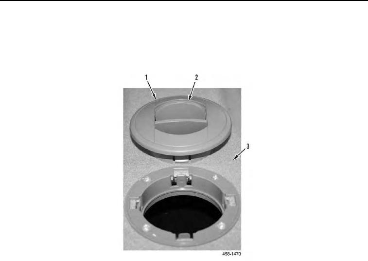
2. Install round vent (Figure 15, Item 1) on bezel (Figure 15, Item 3).
3. Make sure louver (Figure 15, Item 2) opens and closes properly.
Figure 15. Round Vent, Bezel, and Headliner.
0133
0133-10


Privacy Statement
Press Release
Contact

© Copyright Integrated Publishing, Inc.. All Rights Reserved.