
TM 5-3805-298-23-1
0002
LOCATION AND DESCRIPTION OF MAJOR COMPONENTS CONTINUED
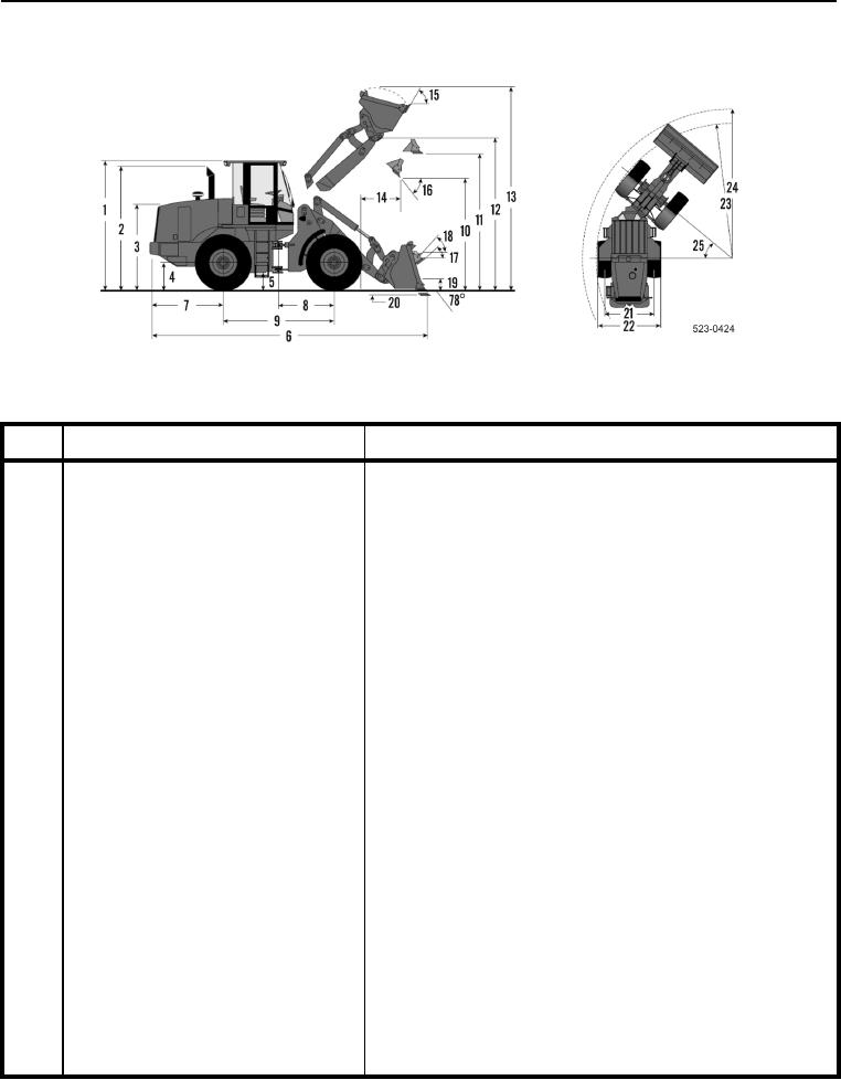
Figure 8. 924H Dimensions with MP Bucket.
0002
DIMENSION
KEY
COMPONENT
Height to top of ROPS/FOPS cab
128 in. (3.3 m)
1
2
Height to top of exhaust stack
124 in. (3.159 m)
3
Height to top of hood
85 in. (216.7 m)
4
Height to center of axle
25 in. (64.0 cm)
5
Ground clearance
15 in. (43.2 cm)
6
Overall length
301 in. (7.16 m)
7
Length - rear axle to bumper
82 in. (2.08 m)
8
Centerline of front axle to frame articu-
55 in. (1.4 m)
lation point
9
Wheelbase
110 in. (2.8 m)
10
Dump clearance at maximum lift and
97 in. (2.462 m)
45-degree dump
11
Bucket clearance at maximum lift and
133 in. (3.376 m)
level
12
Bucket pin height at maximum lift
151 in. (3.82 m)
13
Overall height - bucket raised
200 in. (5.071 m)
14
Reach at maximum lift and 45-degree
40 in. (102 cm)
dump
15
Rack back (tilt) angle at maximum lift
58 degrees
16
Dump angle at maximum lift
45 degrees
17
Rack back (tilt) angle at ground
50 degrees
18
Rack back (tilt) angle at carry
51 degrees