
TM 5-3805-298-23-2
0210
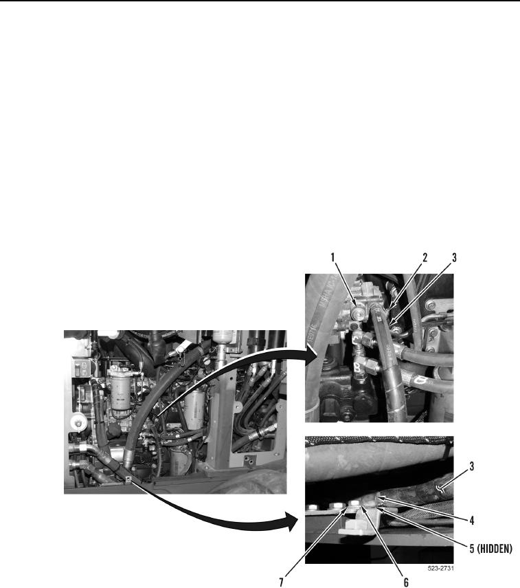
FUEL INJECTION PUMP SUPPLY HOSE INSTALLATION
000210
1. Position fuel injection pump supply hose (Figure 25, Item 3) on machine.
CAUTION
Remove all caps from fuel line openings and component connections during installation.
Failure to follow this caution may result in damage to equipment.
NOTE
Refer to removal for fuel injection pump supply hose routing.
2. Install fuel injection pump supply hose (Figure 25, Item 3) and tighten clamp (Figure 25, Item 2) on fuel
injection pump (Figure 25, Item 1).
3. Install P-clamp (Figure 25, Item 4) on fuel injection pump supply hose (Figure 25, Item 3).
4. Install two P-clamps (Figure 25, Items 4 and 5), washer (Figure 25, Item 7), and bolt (Figure 25, Item 6) on
machine.
Figure 25. Fuel Injection Pump Supply Hose.
0210