
TM 5-3805-298-23-2
0217
REMOVAL CONTINUED
NOTE
Cap all hose ends.
Tag all hoses to aid installation.
Note routing of hoses to aid installation.
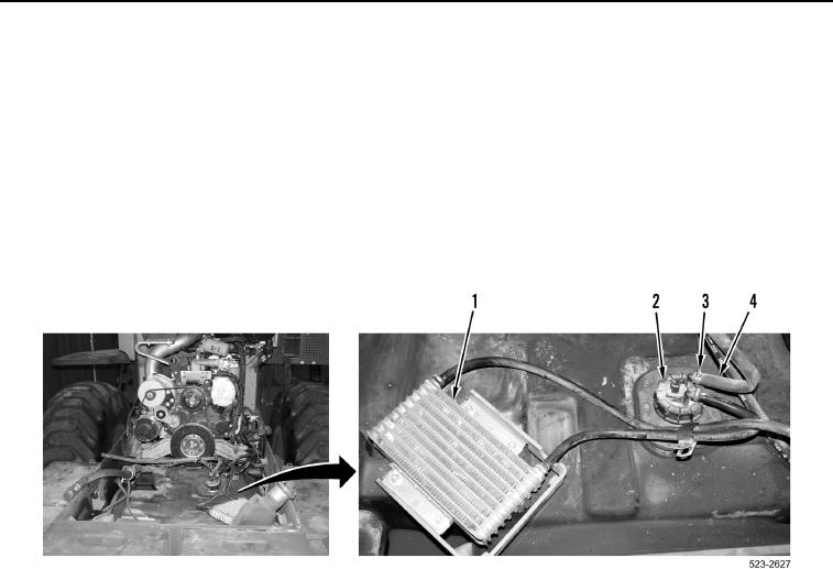
3. Loosen two clamps (Figure 2, Item 3) and remove two hoses (Figure 2, Item 4) from fuel sending unit
(Figure 2, Item 2).
4. Position fuel cooler (Figure 2, Item 1) and two hoses (Figure 2, Item 4) aside.
Figure 2. Fuel Cooler Hoses.
0217