
TM 5-3805-298-23-2
0217
REMOVAL CONTINUED
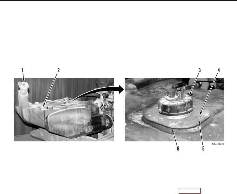
14. Remove fuel cap (Figure 9, Item 1) from fuel tank (Figure 9, Item 2).
NOTE
Note position and orientation of fuel sending unit to aid installation.
15. Remove eight bolts (Figure 9, Item 4), washers (Figure 9, Item 5), fuel sending unit (Figure 9, Item 3), and
gasket (Figure 9, Item 6) from fuel tank (Figure 9, Item 2). Discard gasket.
Figure 9. Fuel Sending Unit.
0217
END OF TASK
CLEANING AND INSPECTION
000217
Clean and inspect all components IAW Mechanical General Maintenance Instructions (WP 0172).
END OF TASK