
TM 5-3805-298-23-2
0218
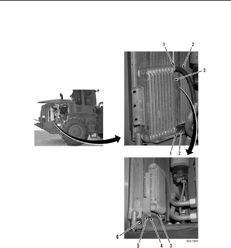
INSTALLATION CONTINUED
2. Position fuel cooler (Figure 4, Item 3) on machine.
3. Install two washers (Figure 4, Item 5) and bolts (Figure 4, Item 4) on bracket (Figure 4, Item 6).
4. Install two hoses (Figure 4, Item 2) and clamps (Figure 4, Item 1) on fuel cooler (Figure 4, Item 3).
Figure 4. Fuel Cooler Bottom Bracket.
0218
END OF TASK
FOLLOW-ON TASKS
000218
Verify correct operation of machine (TM 5-3805-298-10).
END OF TASK
END OF WORK PACKAGE