
TM 5-3805-298-23-2
0234
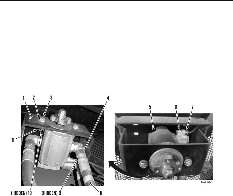
GEAR MOTOR AND DEMAND FAN SOLENOID INSTALLATION CONTINUED
NOTE
Install hoses and wiring harness connectors as noted during removal.
Install tiedown straps as noted during removal.
Remove caps from hoses and fittings prior to installation.
5. Install gear motor (Figure 11, Item 5), two washers (Figure 11, Item 2), bolts (Figure 11, Item 3), washers
(Figure 11, Item 10), and nuts (Figure 11, Item 11) on fan support (Figure 11, Item 1).
6. Connect rear frame wiring harness connector (Figure 11, Item 7) to demand fan solenoid (Figure 11, Item 6).
7. Install three new O-rings (Figure 11, Item 9) and hoses (Figure 11, Item 8) on gear motor (Figure 11, Item 5).
Tighten tube nuts (Figure 11, Item 4).
Figure 11. Gear Motor.
0234