
TM 5-3805-298-23-4
0366
INSTALLATION CONTINUED
NOTE
Install electrical connectors and route wiring harness as noted during removal.
Install tiedown straps as noted during removal.
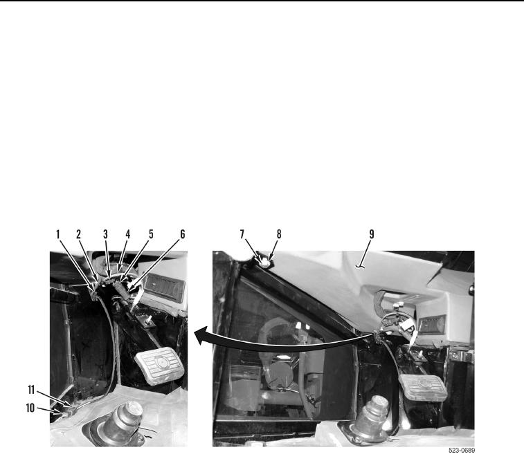
10. Install four washers (Figure 9, Item 8) and bolts (Figure 9, Item 7) on dash (Figure 9, Item 9)
11. Connect front wiper motor connector (Figure 9, Item 6) on main cab wiring harness connector
(Figure 9, Item 5).
12. Connect brake pedal connector (Figure 9, Item 3) on main cab wiring harness connector (Figure 9, Item 4).
13. Connect differential lock wiring harness connector (Figure 9, Item 10) on main cab wiring harness connector
(Figure 9, Item 11).
14. Install new tiedown straps (Figure 9, Item 1) on main cab wiring harness (Figure 9, Item 2).
Figure 9. Left Side Harness Connections.
0366