
TM 5-3805-298-23-4
0407
REMOVAL CONTINUED
WARNING
DO NOT service cooling system unless engine has cooled. This is a pressurized cooling
system and escaping steam or hot coolant will cause serious burns.
Wear effective eye, glove, and skin protection when handling coolants.
Failure to follow these warnings may cause injury or serious burns to personnel.
NOTE
Care must be taken to ensure that fluids are contained during performance of inspection,
maintenance, testing, adjusting and repair of the product. Be prepared to collect the fluid
with suitable containers before opening any compartment or disassembling any
component containing fluids.
Dispose of all fluids according to local regulations and mandates.
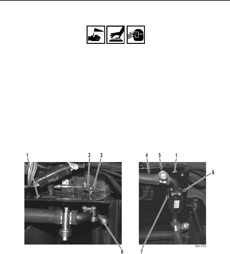
13. Remove retaining clip (Figure 7, Item 3) and lever (Figure 7, Item 2) from heater valve (Figure 7, Item 6).
14. Remove two clamps (Figure 7, Item 5) and hoses (Figure 7, Item 4) from heater valve (Figure 7, Item 6).
15. Remove four screws (Figure 7, Item 7) and heater valve (Figure 7, Item 6) from bracket (Figure 7, Item 1).
Figure 7. Heater Valve.
0407
END OF TASK