
TM 5-3805-298-23-4
0409
REMOVAL CONTINUED
000409
NOTE
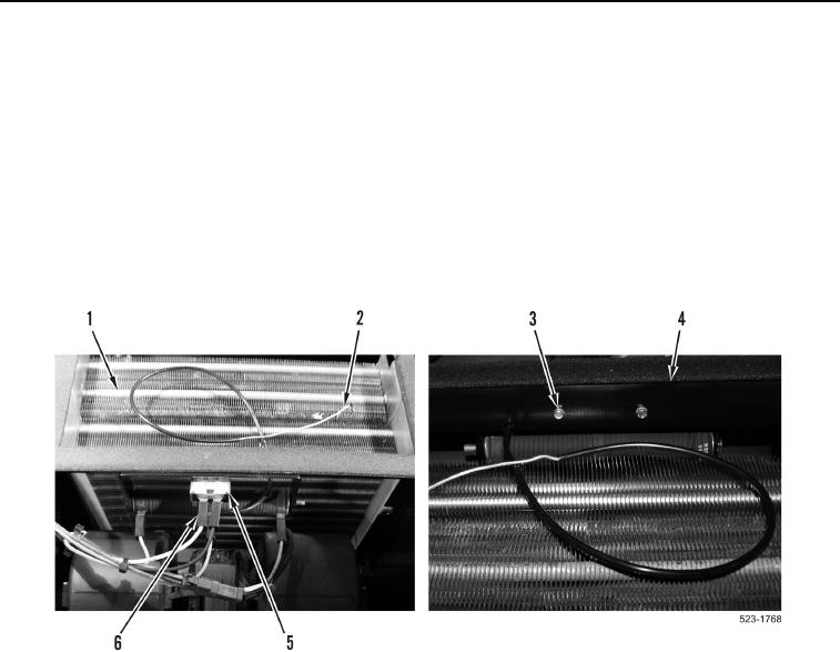
Tag and note location of wiring harness connectors to aid installation.
Note routing of capillary tube to aid installation.
14. Disconnect two lower cab wiring harness terminals (Figure 8, Item 6) from cab heater and A/C temperature
switch (Figure 8, Item 5).
15. Carefully remove capillary tube (Figure 8, Item 2) from evaporator (Figure 8, Item 1).
16. Remove two bolts (Figure 8, Item 3) and cab heater and A/C temperature switch (Figure 8, Item 5) from
bracket (Figure 8, Item 4). Carefully pull capillary tube (Figure 8, Item 2) through bracket.
Figure 8. Cab Heater and A/C Temperature Switch.
0409
END OF TASK
CLEANING AND INSPECTION
000409
Clean and inspect all parts IAW Electrical General Maintenance Instructions (WP 0174).
END OF TASK
INSTALLATION
000409
NOTE
Install wiring harness connectors and capillary tube as noted during removal.
1. Carefully feed capillary tube (Figure 8, Item 2) through bracket and install cab heater and A/C temperature
switch (Figure 8, Item 5) and two bolts (Figure 8, Item 3) on bracket (Figure 8, Item 4).
2. Carefully install capillary tube (Figure 8, Item 2) in evaporator (Figure 8, Item 1).
3. Connect two wiring harness terminals (Figure 8, Item 6) to cab heater and A/C temperature switch
(Figure 8, Item 5).