
TM 5-2420-231-23-1
0019
Table 1. Tachometer Does Not Function or Is Inaccurate - Continued.
019
MALFUNCTION
TEST OR INSPECTION
CORRECTIVE ACTION
Test Step 4. Test Tachometer Output
Tachometer Does Not
Terminal on Alternator.
Function or Is Inaccurate -
Continued
1. Turn ignition switch to the off posi-
tion (TM 5-2420-231-10) and dis-
connect batteries (WP 0157).
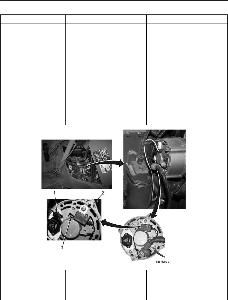
2. Disconnect "W" terminal connector
(Figure 5, Item 1) from "W" termi-
nal (Figure 5, Item 3) on alternator
(Figure 5, Item 2).
3. Connect batteries (WP 0157) and
start and idle engine (TM 5-2420-
231-10).
4. Using a digital multimeter, test for
Voltage 10 to 14 Volts - Proceed to
voltage between "W" terminal
Test Step 5.
(Figure 5, Item 3) on alternator
Voltage Less Than 10 Volts - Replace
(Figure 5, Item 2) and machine
alternator (WP 0153).
ground. Voltage should be 10 to 14
Proceed to Test Step 6.
volts.
Figure 5. Alternator Connections.
0019
Test Step 5. Test Tachometer Signal
Circuit.
1. Turn ignition switch to the off posi-
tion (TM 5-2420-231-10) and dis-
connect batteries (WP 0157).