
TM 5-2420-231-23-1
0032
Table 1. A/C Compressor Does Not Operate - Continued.
032
MALFUNCTION
TEST OR INSPECTION
CORRECTIVE ACTION
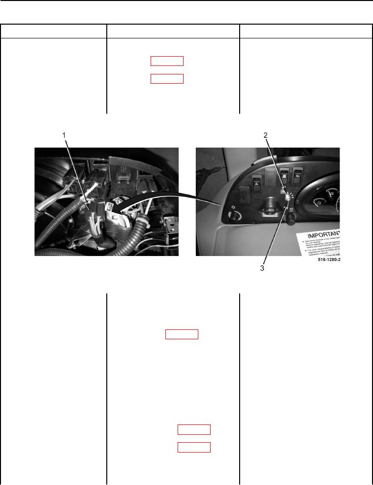
5. Disconnect side console wiring
A/C Compressor Does Not
harness connector (Figure 6,
Operate - Continued
Item 1) (WP 0007, Figure 145)
from blower fan switch (Figure 6,
Item 3) (WP 0007, Figure 144).
6. Remove nut (Figure 6, Item 2) and
blower fan switch (Figure 6,
Item 3).
Figure 6. Blower Fan Switch and Side Console Wiring Harness Connector.
0032
7. Using a digital multimeter, mea-
Resistance 5.0 Ohms or Less -
sure resistance between blower
Proceed to Test Step 4.
fan switch 12-volt supply terminal
Resistance Greater Than 5.0 Ohms -
and A/C compressor voltage sup-
Replace fan speed switch (WP 0172).
ply terminal (WP 0007, Figure
Proceed to Test Step 9.
144), while rotating blower fan
switch to each speed setting (TM
5-2420-231-10). Resistance
should be 5.0 ohms or less.
Test Step 4. Test for an Open Circuit
in Side Console Wiring Harness.
1. Remove rear instrument right-side
cover (WP 0176).
2. Disconnect side options wiring har-
ness connector (WP 0007, Figure
44) from side console wiring har-
ness connector (WP 0007, Figure
45).