TM 5-2420-231-23-1
0051
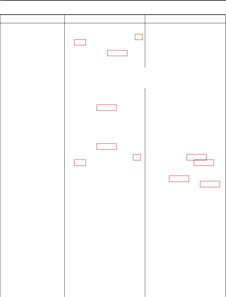
Table 1. Transmission Does Not Shift into Forward - Continued.
051
MALFUNCTION
TEST OR INSPECTION
CORRECTIVE ACTION
5. Using a digital multimeter, mea-
Transmission Does Not Shift
Resistance 5.0 Ohms or Less -
sure resistance between power-
Proceed to step 6.
into Forward - Continued
shift wiring harness connector (WP
Resistance Greater Than 5.0 Ohms -
0007, Figure 113) terminal C and
Install instrument panel front cover (WP
powershift controller wiring har-
0174).
ness connector (WP 0007, Figure
Replace powershift wiring harness (WP
21) terminal 7. Resistance should
0167).
be 5.0 ohms or less.
Proceed to Test Step 38.
NOTE
Powershift lever remains in the F position (TM 5-2420-231-10) during this
test.
6. Using a digital multimeter, mea-
Resistance 5.0 Ohms or Less -
sure resistance between power-
Proceed to step 6.
shift lever wiring harness
Resistance Greater Than 5.0 Ohms -
connector (WP 0007, Figure 114)
Install instrument panel front cover (WP
terminals 7 and 8. Resistance
0174).
should be 5.0 ohms or less.
Replace powershift lever (WP 0165).
Proceed to Test Step 38.
7. Using a digital multimeter, mea-
Resistance 5.0 Ohms or Less - Turn
sure resistance between power-
ignition switch to the off position (TM 5-
shift controller wiring harness
2420-231-10) and disconnect batteries
connector (WP 0007, Figure 21)
(WP 0157).
terminal 8 and powershift control-
Connect powershift controller wiring
ler wiring harness connector (WP
harness connector (WP 0007, Figure
0007, Figure 20) terminal A1.
21) to powershift lever (WP 0007,
Resistance should be 5.0 ohms or
Figure 114).
less.
Connect front console wiring harness
connector (WP 0007, Figure 112) to
powershift wiring harness (WP 0007,
Figure 113).
Proceed to Test Step 28.
Resistance Greater Than 5.0 Ohms -
Install instrument panel front cover (WP
0174).
Replace powershift wiring harness (WP
0167).
Proceed to Test Step 38.
Test Step 28. Test Forward Relay
Switch Side Voltage Supply and
Ground Circuit.
1. Place powershift lever in the N
position (TM 5-2420-231-10).
2. Connect batteries (WP 0157) and
turn ignition switch to the on posi-
tion (TM 5-2420-231-10).
3. Place powershift lever in the F
position (TM 5-2420-231-10).
0051-35

