
TM 5-2420-231-23-1
0073
Table 1. Multiple Backhoe Operations (Pilot Controls) Do Not Function Correctly - Continued.
073
MALFUNCTION
TEST OR INSPECTION
CORRECTIVE ACTION
5. Using a digital multimeter, mea-
Resistance 5.0 Ohms or Less - Install
Multiple Backhoe
sure resistance between front con-
pilot controls fuse (TM 5-2420-231-10).
Operations (Pilot Controls)
sole wiring harness connector (WP
Replace main chassis wiring harness
Do Not Function Correctly -
0007, Figure 5) terminal 5N and
(WP 0154).
Continued
front console fuse block connector
Proceed to Test Step 29.
(WP 0007, Figure 70) terminal
Resistance Greater Than 5.0 Ohms -
11A. Resistance should be 5.0
Replace front console wiring harness
ohms or less.
(WP 0162).
Proceed to Test Step 29.
Test Step 10. Test for Shorted Wiring
Harness.
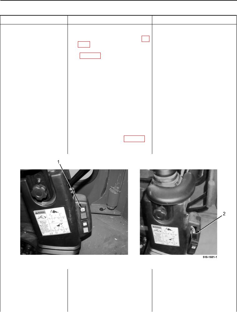
1. Pull pilot control switch (Figure 3,
Item 1) from right-hand backhoe
tower and disconnect right-hand
backhoe tower wiring harness con-
nector (Figure 3, Item 2) from pilot
control switch.
2. Using a digital multimeter, test for
Continuity - Proceed to Test Step 11.
continuity between right-hand
No Continuity - Proceed to Test Step
tower wiring harness (WP 0007,
14.
Figure 163) terminals 5 and 7.
There should be no continuity.
Figure 3. Pilot Control Switch.
0073