
20
TM 5-2420-231-23-1
FIELD MAINTENANCE
-
FUEL SYSTEM TESTS, INSPECTIONS, AND ADJUSTMENTS
00
85
Finding Top Dead Center (TDC), Checking Fuel Injection Pump Timing, Throttle Cable Adjustment,
Fuel System Prime Procedure
INITIAL SETUP
Tools and Special Tools
Personnel Required
Tool Kit, General Mechanic's
Two
0
0
(WP 0376, Item 117)
References
Gage, Pressure, Dial Indicating, 0-5 mm
0
WP 0112
(WP 0376, Item 26)
0
WP 0148
Pin, Grooved Head (WP 0376, Item 55)
0
0
WP 0149
Puller, Mechanical (Injector)
0
0
WP 0152
(WP 0376, Item 66)
0
Rotation Tool, Engine (WP 0376, Item 75)
Equipment Conditions
0
Socket Driver, 3/8" Dr., Chrome, Torx, T25
0
Front end loader raised with safety support
0
(WP 0376, Item 89)
strut engaged (TM 5-2420-231-10)
Stop, Mechanical (WP 0376, Item 103)
0
Materials/Parts
Rag, Wiping (WP 0375, Item 25)
0
FINDING TOP DEAD CENTER (TDC)
0085
1. Remove front and rear valve covers (WP 0112).
2. Remove starter (WP 0152).
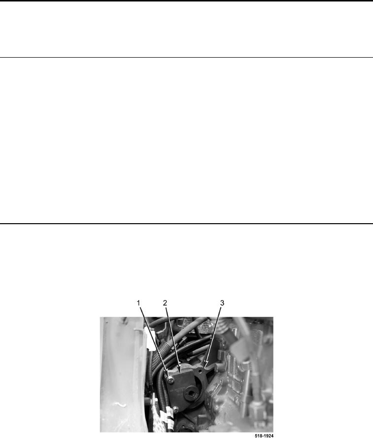
3. Install engine turning tool (Figure 1, Item 2) and two starter bolts (Figure 1, Item 1) on engine
(Figure 1, Item 3).
Figure 1. Engine Turning Tool.
0085