
TM 5-2420-231-23-2
0104
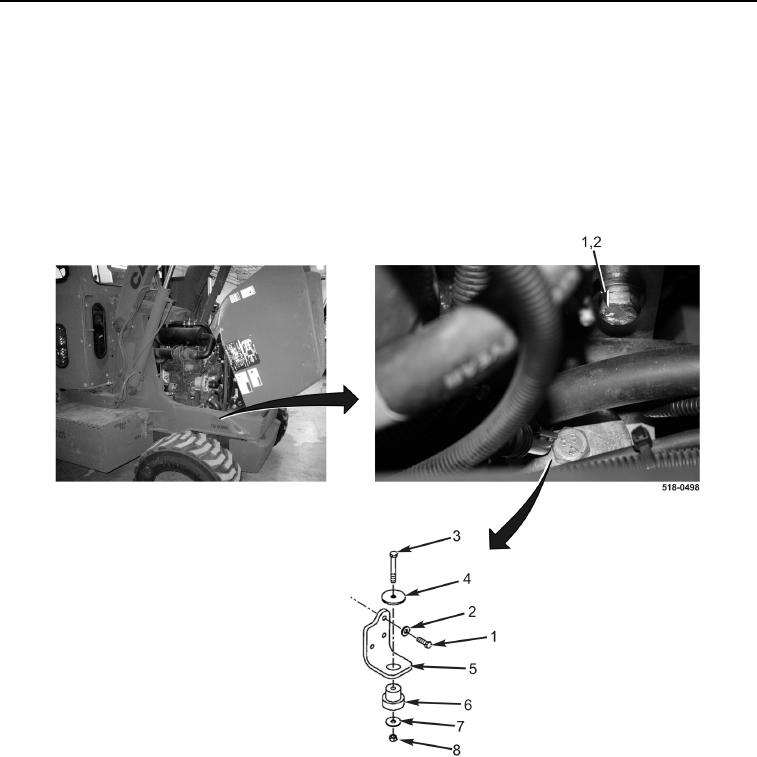
REMOVAL CONTINUED
3. Remove bolt (Figure 2, Item 3), locknut (Figure 2, Item 8), and two washers (Figure 2, Items 4 and 7) from
engine mounting bracket (Figure 2, Item 5). Discard locknut.
4. Use lifting device to slightly raise front of engine.
5. Remove three bolts (Figure 2, Item 1), washers (Figure 2, Item 2), engine mounting bracket (Figure 2, Item 5),
and resilient mount (Figure 2, Item 6) from machine.
6. Remove resilient mount (Figure 2, Item 6) from engine mounting bracket (Figure 2, Item 5).
7. Lower lifting device slightly.
Figure 2. Right Resilient Mount and Bracket.
0104