
TM 5-2420-231-23-2
0105
REMOVAL CONTINUED
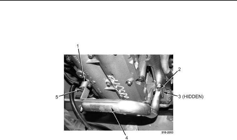
5. Remove bolt (Figure 5, Item 5) and spacer (Figure 5, Item 1) from engine.
6. Remove two bolts (Figure 5, Item 2), oil pump strainer (Figure 5, Item 4), and gasket (Figure 5, Item 3) from
engine. Discard gasket.
Figure 5. Oil Pump Strainer.
0105
END OF TASK
CLEANING AND INSPECTION
00105
Clean and inspect all parts IAW Mechanical General Maintenance Instructions (WP 0369).
END OF TASK
INSTALLATION
00105
1. Install new gasket (Figure 5, Item 3), oil pump strainer (Figure 5, Item 4), and two bolts (Figure 5, Item 2) on
engine. Torque bolts to 15-21 lb-ft (20-28 Nm).
2. Install spacer (Figure 5, Item 1) and bolt (Figure 5, Item 5) on engine. Torque bolt to 15-21 lb-ft (20-28 Nm).