
TM 5-2420-231-23-2
0105
REMOVAL CONTINUED
3. Remove four bolts (Figure 3, Item 3), two clamps (Figure 3, Item 1), and drive shaft (Figure 3, Item 2) from
machine.
Figure 3. Drive Shaft.
0105
NOTE
Note position of bolts to aid in installation.
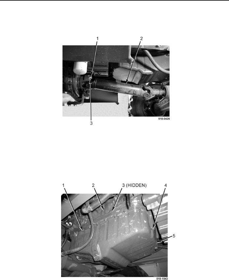
4. With assistance, remove 22 bolts (Figure 4, Item 1), 2 bolts (Figure 4, Item 4), oil pan (Figure 4, Item 5), and
gasket (Figure 4, Item 3) from engine (Figure 4, Item 2). Discard gasket.
Figure 4. Oil Pan.
0105