
TM 5-2420-231-23-2
0118
REMOVAL CONTINUED
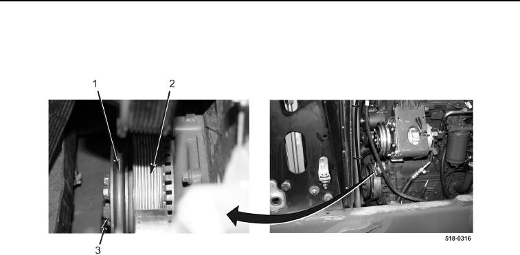
2. With assistance, remove six bolts (Figure 2, Item 3), front crankshaft pulley (Figure 2, Item 1), and rear crank-
shaft pulley (Figure 2, Item 2) from machine.
Figure 2. Crankshaft Pulleys.
0118
END OF TASK
CLEANING AND INSPECTION
0118
Clean and inspect all parts IAW Mechanical General Maintenance Instructions (WP 0369).
END OF TASK
INSTALLATION
0118
1. With assistance, install rear crankshaft pulley (Figure 2, Item 2), front crankshaft pulley (Figure 2, Item 1), and
six bolts (Figure 2, Item 3) on machine. Tighten bolts to 77-85 lb-ft (105-115 Nm).