
TM 5-2420-231-23-2
0117
REMOVAL CONTINUED
NOTE
Note orientation of flywheel to aid in installation.
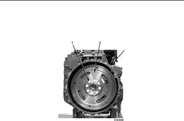
2. With assistance, remove eight bolts (Figure 2, Item 1) and flywheel (Figure 2, Item 2) from engine.
Figure 2. Flywheel Bolts.
0117
END OF TASK
CLEANING AND INSPECTION
0117
Clean and inspect all parts IAW Mechanical General Maintenance Instructions (WP 0369).
END OF TASK
INSTALLATION
0117
NOTE
Install flywheel as noted during removal.
1. Install flywheel (Figure 2, Item 2) and eight bolts (Figure 2, Item 1) on engine. Hand-tighten bolts.
2. With assistance, tighten flywheel bolts (Figure 2, Item 1) in a criss-cross pattern to 26 lb-ft (35 Nm).
3. With assistance, tighten flywheel bolts (Figure 2, Item 1) an additional 60 degrees in a criss-cross pattern.