
TM 5-2420-231-23-2
0140
REMOVAL CONTINUED
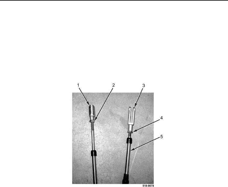
18. Loosen jamnut (Figure 10, Item 2) and remove retainer (Figure 10, Item 1) from foot throttle cable
(Figure 10, Item 5).
19. Remove jamnut (Figure 10, Item 2) from foot throttle cable (Figure 10, Item 5).
NOTE
Note position and orientation of clevis to aid in installation.
20. Loosen jamnut (Figure 10, Item 4) and remove clevis (Figure 10, Item 3) from foot throttle cable
(Figure 10, Item 5).
21. Remove jamnut (Figure 10, Item 4) from foot throttle cable (Figure 10, Item 5).
Figure 10. Foot Throttle Cable Fittings.
0140
END OF TASK
CLEANING AND INSPECTION
0140
Clean and inspect all parts IAW Mechanical General Maintenance Instructions (WP 0369).
END OF TASK
INSTALLATION
0140
NOTE
Install clevis in position and orientation noted in removal.
1. Install jamnut (Figure 10, Item 4) on foot throttle cable (Figure 10, Item 5).
2. Install clevis (Figure 10, Item 3) on foot throttle cable (Figure 10, Item 5) and tighten jamnut (Figure 10, Item 4).
3. Install jamnut (Figure 10, Item 2) on foot throttle cable (Figure 10, Item 5).
4. Install retainer (Figure 10, Item 1) on foot throttle cable (Figure 10, Item 5) and tighten jamnut
(Figure 10, Item 2).