
TM 5-2420-231-23-2
0140
INSTALLATION CONTINUED
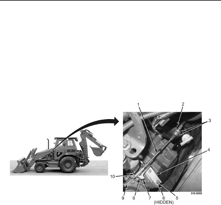
5. Install throttle bracket (Figure 11, Item 4), two new lockwashers (Figure 11, Item 6), and bolts (Figure 11,
Item 5) on fuel injection pump (Figure 11, Item 9).
6. Install ball stud (Figure 11, Item 8) and new locknut (Figure 11, Item 7) on fuel injection pump
(Figure 11, Item 9).
NOTE
Route foot throttle cable as noted during removal.
7. Install foot throttle cable (Figure 11, Item 1) on machine.
8. Install foot throttle cable (Figure 11, Item 1) on ball stud (Figure 11, Item 8) and secure retainer
(Figure 11, Item 10).
9. Install foot throttle cable (Figure 11, Item 1) on bracket (Figure 11, Item 2) and tighten two jamnuts
(Figure 11, Item 3).
Figure 11. Fuel Injection Pump Connection.
0140