
TM 5-2420-231-23-2
0153
REMOVAL CONTINUED
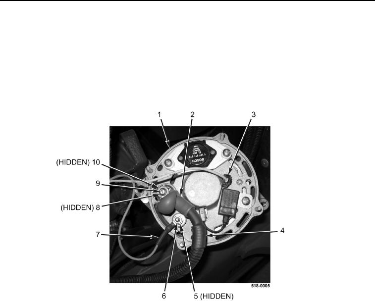
7. Disconnect "W" connector (Figure 3, Item 3) from alternator (Figure 3, Item 1).
8. Position boot (Figure 3, Item 2) aside and remove nut (Figure 3, Item 9), lockwasher (Figure 3, Item 8), "B+"
cable (Figure 3, Item 4), and lockwasher (Figure 3, Item 10) from alternator (Figure 3, Item 1). Discard lock-
washers.
9. Remove nut (Figure 3, Item 6), lockwasher (Figure 3, Item 5), and "D+" wire (Figure 3, Item 7) from alternator
(Figure 3, Item 1). Discard lockwasher.
10. Remove alternator (Figure 3, Item 1) from machine.
Figure 3. Alternator Connections.
0153