
TM 5-2420-231-23-2
0187
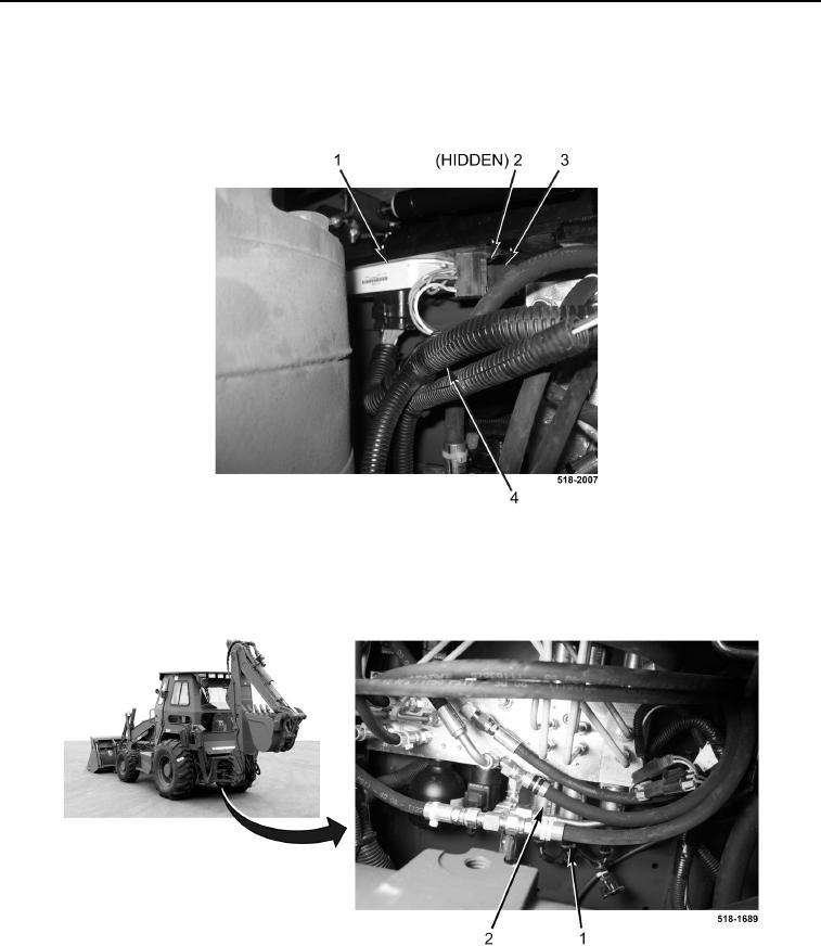
INSTALLATION CONTINUED
7. Connect pilot controls wiring harness (Figure 12, Item 4) to control unit (Figure 12, Item 1).
8. Install screw (Figure 12, Item 2) on pilot controls wiring harness (Figure 12, Item 4).
9. Connect relay (Figure 12, Item 3) to pilot controls wiring harness (Figure 12, Item 4).
Figure 12. Control Unit and Relay.
0187
10. Connect nine pilot controls wiring harness connectors (Figure 13, Item 1) to pilot control valve solenoids
(Figure 13, Item 2).
Figure 13. Pilot Control Valve.
0187