
TM 5-2420-231-23-2
0203
INSTALLATION
0203
NOTE
Tires are directional. Refer to tire sidewall for direction of rotation.
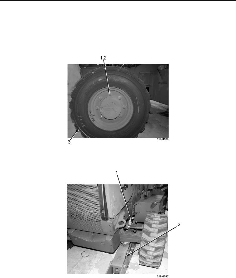
1. Install wheel and tire assembly (Figure 6, Item 3), eight washers (Figure 6, Item 2), and nuts (Figure 6, Item 1)
on machine. Tighten to 185 lb-ft (251 Nm).
Figure 6. Wheel and Tire Assembly.
0203
2. Remove trestle (Figure 7, Item 1), lower machine, and remove suitable lifting device (Figure 7, Item 2) from
under machine.
Figure 7. Lifting Device and Trestle.
0203
END OF TASK
END OF WORK PACKAGE