
TM 5-2420-231-23-2
0213
REMOVAL CONTINUED
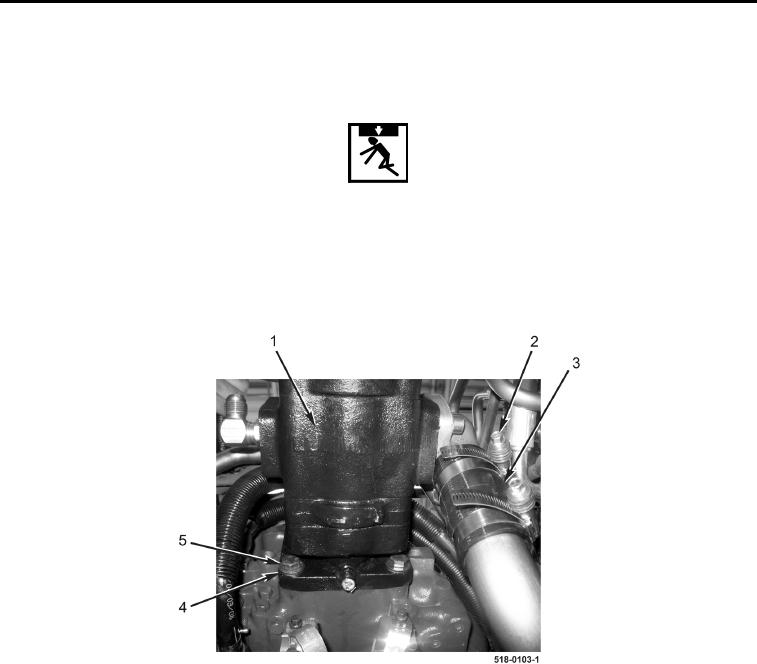
29. Loosen hose clamp (Figure 8, Item 2) and disconnect hose (Figure 8, Item 3) from hydraulic pump
(Figure 8, Item 1).
WARNING
Remove bottom two bolts first to avoid working underneath the pump while the bolts are
removed. Failure to follow this warning may result in injury or death to personnel.
30. Attach nylon sling to hydraulic pump (Figure 8, Item 1).
31. Remove two bottom bolts (Figure 8, Item 5) and washers (Figure 8, Item 4) from hydraulic pump
(Figure 8, Item 1).
Figure 8. Hydraulic Pump Bottom Bolts.
0213