
TM 5-2420-231-23-2
0213
REMOVAL CONTINUED
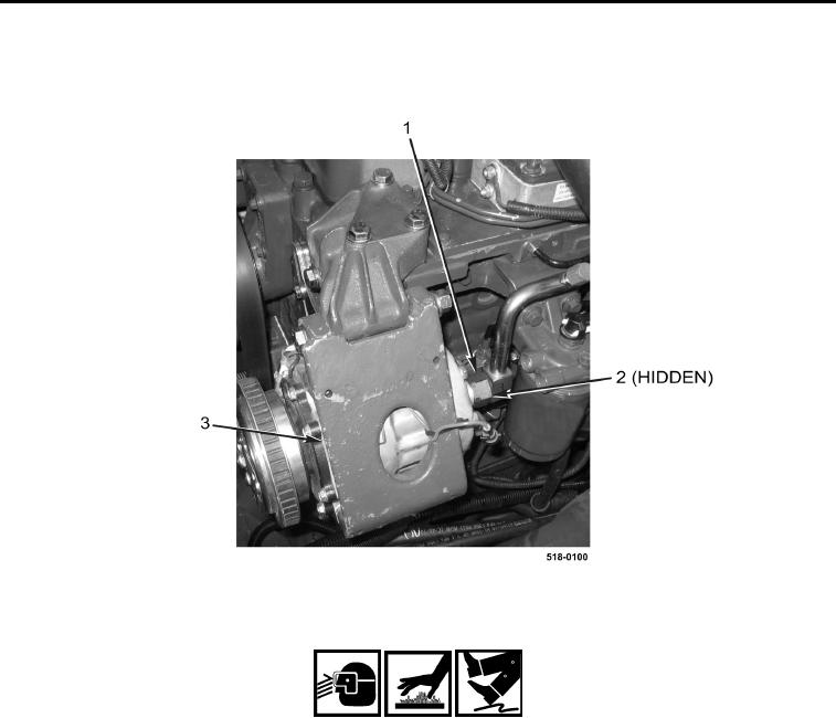
20. Disconnect hose (Figure 5, Item 1) and remove O-ring (Figure 5, Item 2) from A/C compressor assembly
(Figure 5, Item 3). Discard O-ring.
Figure 5. A/C Compressor.
0213
WARNING
Allow hydraulic system to cool before performing procedure. Hot hydraulic fluid can cause
severe burns. Wear eye, hand, and skin protection when working with heated parts.
Hydraulic oil is very slippery. Immediately wipe up any spills.
Failure to follow these warnings may result in injury or death to personnel.
CAUTION
Plug and cap all hoses and fittings to prevent contamination. Failure to follow this caution
may result in damage to the machine.
NOTE
Note the routing, position, and orientation of hydraulic hoses to aid in installation.
Tag and mark hoses to aid in installation.
21. Disconnect steering (LS) hose (Figure 6, Item 3) from fitting (Figure 6, Item 6).
22. Disconnect quick-coupler (LS) hose (Figure 6, Item 7) from fitting (Figure 6, Item 6).
23. Disconnect pressure hose (Figure 6, Item 10) from fitting (Figure 6, Item 1).