
TM 5-2420-231-23-2
0213
REMOVAL CONTINUED
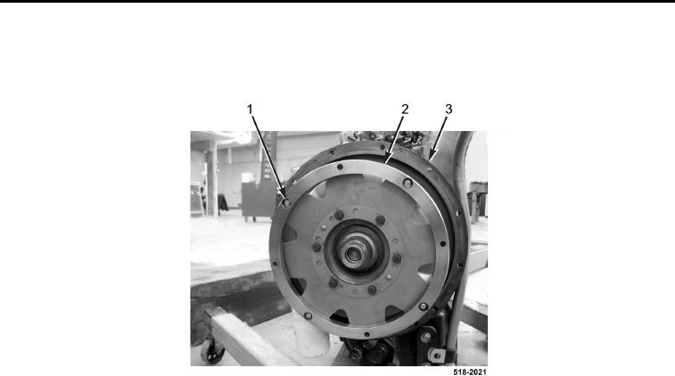
68. Remove four bolts (Figure 25, Item 1) and drive plate ring (Figure 25, Item 2) from transmission
(Figure 25, Item 3).
Figure 25. Drive Plate Ring.
0213
NOTE
Note position and location of fittings to aid in installation.
69. Loosen nut (Figure 26, Item 3) and remove fitting (Figure 26, Item 4) and O-ring (Figure 26, Item 2) from trans-
mission (Figure 26, Item 1). Discard O-ring.
70. Remove temperature sensor (Figure 26, Item 6) from fitting (Figure 26, Item 5).
71. Loosen nut (Figure 26, Item 7) and remove fitting (Figure 26, Item 5) and O-ring (Figure 26, Item 8) from trans-
mission (Figure 26, Item 1). Discard O-ring.
72. Remove dipstick (Figure 26, Item 14) from dipstick tube (Figure 26, Item 13).
73. Loosen nut (Figure 26, Item 12) and remove dipstick tube (Figure 26, Item 13) from fitting (Figure 26, Item 11).
74. Loosen nut (Figure 26, Item 10) and remove fitting (Figure 26, Item 11) and O-ring (Figure 26, Item 9) from
transmission (Figure 26, Item 1). Discard O-ring.