
TM 5-2420-231-23-2
0213
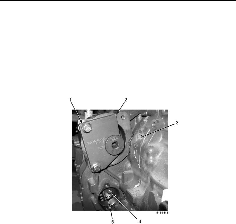
INSTALLATION CONTINUED
19. Install engine turning tool (Figure 33, Item 2) and two bolts (Figure 33, Item 1) on engine (Figure 33, Item 3).
NOTE
It may be necessary to reach through starter hole to align torque converter bolt holes to
engine flywheel.
Torque converter nuts are flexible. It may be necessary to use L-shaped tool to reach
behind flywheel and apply forward pressure on the nuts in order to start bolts.
20. Using engine turning tool, rotate engine and install four bolts (Figure 33, Item 4) on flywheel (Figure 33,
Item 5). Torque to 38-42 lb-ft (52-57 Nm).
21. Remove two bolts (Figure 33, Item 1) and engine turning tool (Figure 33, Item 2) from engine
(Figure 33, Item 3).
Figure 33. Torque Converter Bolts.
0213